State of the Union Address (well sort of)
Wow! Hard to believe that 4-1/2 years have gone by since my last post to this website, where did the time go?
Well part of the reason is I have been working out of town for the past 4-1/2 years on different projects that keep me away from home for months at a time so working on the railroad has pretty much ceased. That is not to say that I have not been doing any modeling, I have but not on the layout.
I am part of the Dirty Thirty On30 modular group here in Ottawa and have built 2 modules for the set-up. These were built while I was working in New York State.
A lot has happened to the layout room during my absence. I share my layout room with the furnace and hot water tank and over the past 3 years I have had to replace the furnace, hot water tank and humidifier. Fortunately, the part of the layout build in front of the furnace was made to be removable as I knew that some day these items would need to be changed. Oh, did I mention the wasp nest that we found in the basement when we came home after being away for a couple of months.
Needless to say, during this time the top of the layout became a “storage space” that turned into a source of frustration every time I went down into the basement. So much so that I stopped going to the basement.
I was asked if I would be willing to open my layout to visitors during a layout tour that took place last October and I used that to get my behind in gear to clean off the layout and clean up the layout room.
It worked. I started with little chunks, starting with the layout space itself. Rather than rearrange things, I decided that everything needed a home, so homes were either made or bought (i.e. storage containers). I also did a lot of purging, it is amazing how much stuff you collect over time thinking that it might be useful someday.
Once the layout space was cleaned up, it was time to clean off the layout. Again, everything was given a new “home” or disposed of. All the buildings were put back in place in the town of Clearwater as they had to be removed to avoid damage when the new furnace was installed. Next step was to put back the removable section of the layout in front of the furnace. I accomplished all this 1 week before the open house, nothing like a deadline for motivation.
Now after 4 years on nothing running on the railway, will it run? Turned the power on, no shorts so I figured that to be a good sign. Dialed in a locomotive with a couple of cars, crossed my fingers and cranked up the throttle. The train started moving, went around the layout and hit a few spots that required cleaning, but overall a lot less effort than what I was expecting.
Last thing to do before the open house was to set up the automatic route for the two switches leading into Mosquito Flats so I would not have to deal with manual operation of these during the open house. The plan was to use a “wabbit” for the two tortoises that control the turnouts. While I could get the turnout to move properly when the locomotive approached the frog of the switch, getting it to align both turnouts proved to be an issue.
Well this lead to a track realignment 2 days before the open house to eliminate the 2 turnouts in question. Wouldn’t have been a challenge if I was using flex track, but all my track is hand laid. Quick measurements indicated that I had barely enough room to lay 2 parallel tracks in the space available so it was off to the races. In the time I had left I barely managed to complete the realignment on time. On the day of the open house the railway ran flawlessly and I was very happy with that result.
Next up I have decided to work on Adams Lake which entails building the trestle bridge, building the log dump, adding the scenery and pouring the water for the lake.
On a separate note I decided to add a column on the left side of the website listing the current updates as they are posted so that one can see if there is a new update or not.
That’s about it for now.
Building the turntable at Mara – Part 2 (The deck)
Now that I have a turntable that will operate reliably it was time to make the deck to accommodate my On30 locomotives. Normally the bridge girders are placed under the rails. This in not a problem in using the HO bridge as the track spacing nor HO and On30 are the same, the difference being a wider deck is required to support the On30 engines.
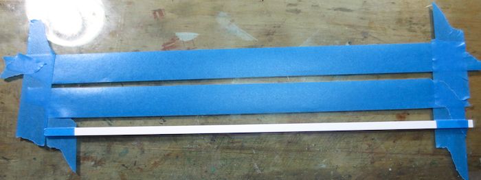
Tape was used to attached a piece of .125 x ,250 styrene to act as a stop to make sure that all the ties when added were in a straight line. Tape was also added sticky side up to hold the ties in place when laid.
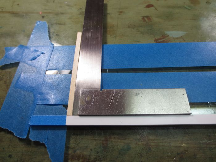
I square was used to make sure that the first tie was 90 degrees to the stop. I used scale 8″ x 8″ for the ties. The ties were cut 12 ft long, the length was picked as it looked right to me.
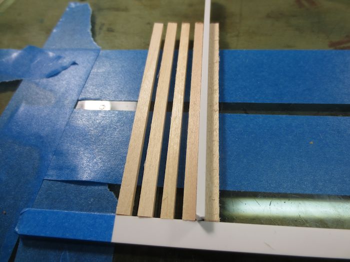
A .060 styrene spacer was used to align the ties to each other. at about every 10th tie I checked the ties with my square to make sure the ties were still 90 degrees to the stop.
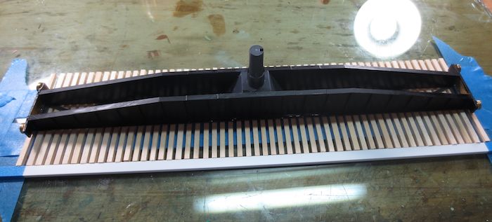
Once all the ties were laid the bridge was centered on the ties and the bridge glued to the ties using 5 minute epoxy.

Scale 8″ x 8″ end rails were glued to the ties.
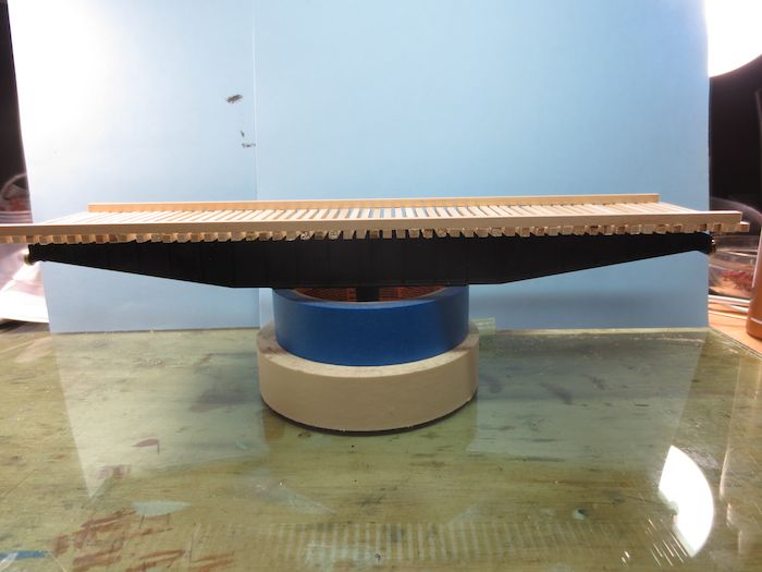
The almost completed deck. The rails were then added along with the planks inside the rails.
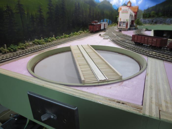
At this point I wanted to make sure that there would be no problems so it was test fitted in place.
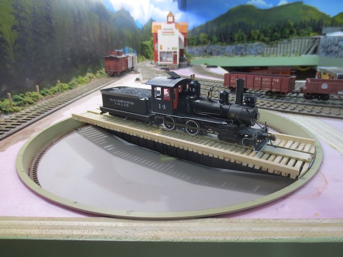
I put one of my 4-4-0’s on the turntable to see how it would look.
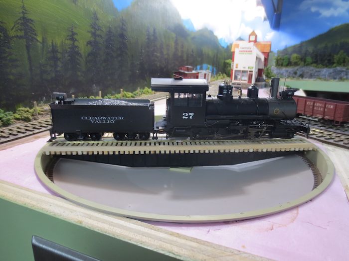
Next up was my Connie which is the longest locomotive I own. Any future locomotive purchases will have to fit on the turntable.
Everything worked great so the bridge was removed and the rest of the deck boards were added and stained to my tie colour. The walls of the pit was painted a concrete colour and I used a “rust” paint marker to paint the rails. Sand and loose dirt was glued to the bottom of the pit to complete the turntable. Care was taken not to get any sand or dirt on the center post as I didn’t want anything to interfere with the operation of the turntable.
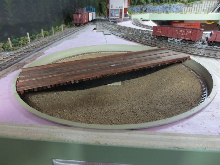
The completed turntable. Now that the deck is added you don’t notice that the outside wheel bracket is missing.
Next up powering the turntable.
Building the Turntable at Mara – Part 1 (the bridge)
The turntable pit in Mara has been in place for a few years now bit hasn’t been completed because of a couple of small design flaws that makes the turntable unreliable. Seeing as I am now having operating sessions I really need a way to turn locomotives without the hand of God involved.
I decided to write this up in three parts, part one will be about fixing the problems with the Bridge, part two will show how I built the deck and part three will be how I powered it.
I am using the Walthers 90ft turntable (HO scale) which works out to 48ft in O scale which is the maximum lengths of my locomotives. The issues I found with the turntable is as follows;
- The walls of the pit were not 90 degrees and had a slight taper which caused the bridge to bind in certain locations.
- The wheels that rode on the pit rails were tapered.
A close-up of the wheels that ride on the pit rail, as you can see from the photo, the wheels are not flat.
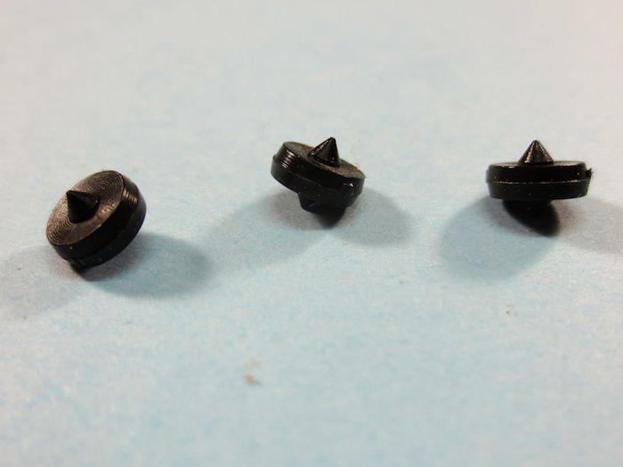
A close up of the the wheels removed from the bridge.
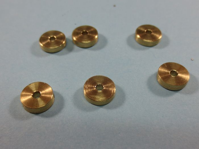
I decided that I would make new wheel assemblies to correct this problem. Using a vernier calliper the diameter of the existing wheels were measured and new wheels were turned on a lathe.
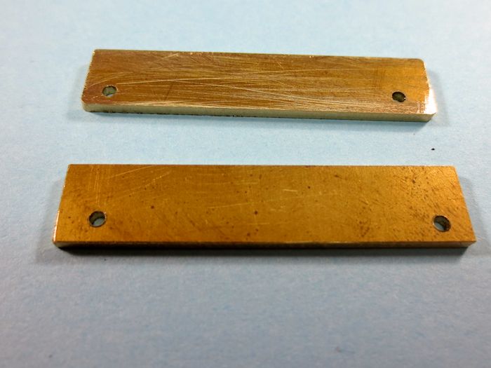
Next brass plates to make the brackets were made to hold the wheels in place on the bridge.
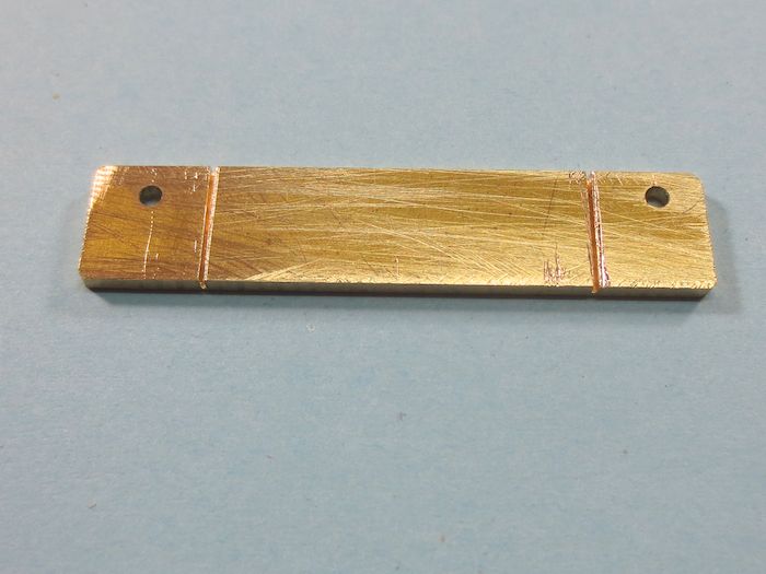
I cut a slot about half way through the brass plates so that they could be bent to match the diameter of the pit rail as the wheels need to be running perpendicular on the pit rail and not on an angle.

Once the plate was bent the wheels were attached. I used brass rod for this and I attached the wheels in the following matter. I put the brass rod into the hole flush with the backside of the plate and soldered the the rod to the plate. I then cut the rod about 1/16″ longer than the width of the wheel. Once the wheel was installed on the rod a jeweller’s hammer was used to add a pien at the end of the rod to make sure that the wheel would stay on the pin.

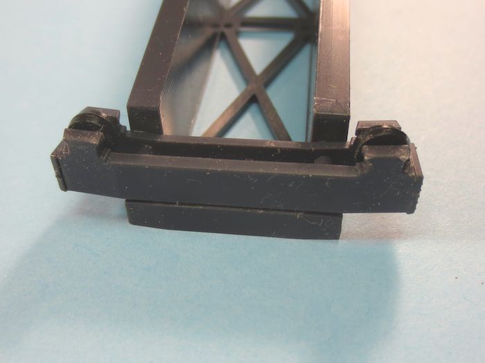
The old bracket and wheel assemblies were removed from the bridge and filed square.
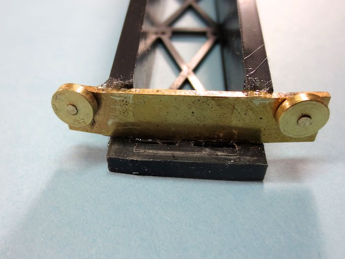
The new bracket and wheel assemblies were epoxied to the bridge. You will notice that there is no outer bracket on the new assembly. THis was done deliberately so that there would be no binding of the new brackets on the pit walls. I could have made narrower wheels and add the outer bracket, but I wanted as much surface area as possible so that there was no chance that the wheels would fall off the pit rail and to allow for any inconsistencies in the diameter of the pit that could have been caused in the moulding process.
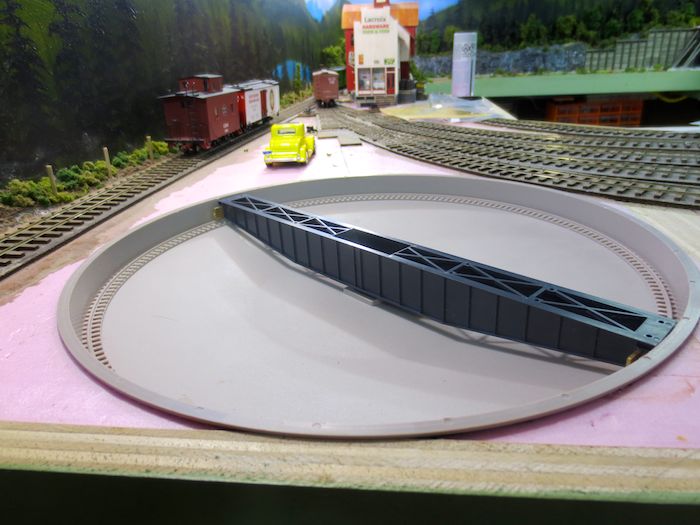
The bridge with it’s new wheel assemblies installed in the pit. I can now turn the bridge in circles with one finger in either direction with no binding whatsoever.
Now that I can get the turntable to operate reliably the next step will be to build the Deck that will go on the top of the bridge. I’ll show how I did this in part two of this turntable saga.
Climbing Mount Everest
Well not really but it does make for a catchy title………
Next on the scenery list is the cliff face at the Okanagan Lumber Camp #4.
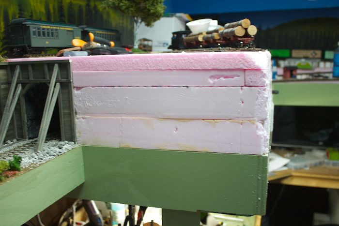
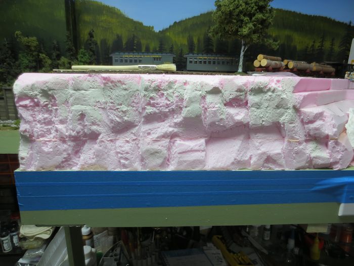
Here is what I have at the lumber camp. I thought of different ways of adding a cliff face such as making plaster rocks and gluing them to the styrofoam but didn’t know how well that would hold up over time seeing as they would overhang the framing. Another option was to use foam rock casting from Mountain-in-Minutes.
I have seen other people carving the rocks and really liked how they looked. I was also directed to a great 2-part video on carving the rocks ( Carving Foam Rocks – Part 1 and Carving Foam Rocks – Part 2 ) After watching the videos a few times I decided to give it a go.
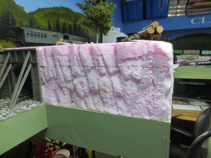
Here is my “attempt” at carving rocks. While the videos give a list of “implements of destruction” to carry out this work I ended up using inly two tools, a cheap steak knife from the dollar store and a 1″ paintbrush that had it bristles cut quite short.
The front side carved.
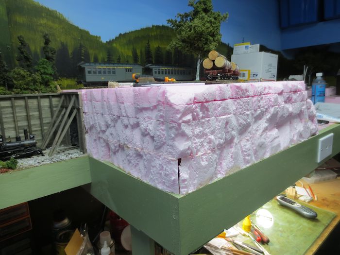
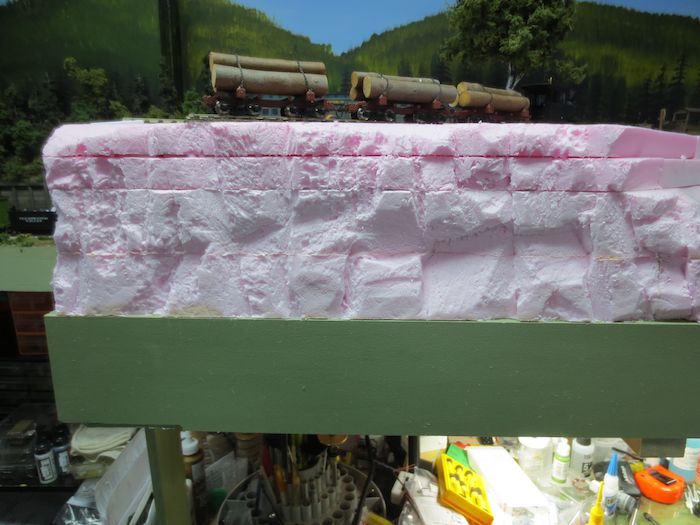
The overall view, as you can see there are some gaps that need to be filled.
To till the gaps I mixed up some plaster of paris and applied it with an artist palette knife. It took longer to mix the plaster than to apply it. I wasn’t too worried at getting it right at this stage asI went back after the plaster had dried and with a #11 blade in a knife I trimmed off any unnatural ridges and/or lumps.

Next it was off to Home Depot to get some grey paint. They sell sell sample sizes for $5.00 each and I picked a grey that was a little lighter than the granite colour I’m looking for.

Once the grey paint was fried I took some Woodland Scenic pigments and with a brush dabbed them on various area of the cliff face. I applied them at full strength and then sprayed them with water to get them into the cracks. The pigments used were raw sienna and burnt sienna.

The front of the rock face completed.
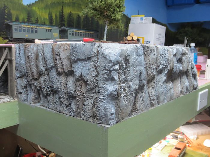
An overall view of the rock face at the Okanagan Lumber Company Camp #4
This turned out easier to do than I expected and looks a heck of a lot better than looking at the pink foam.
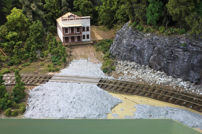
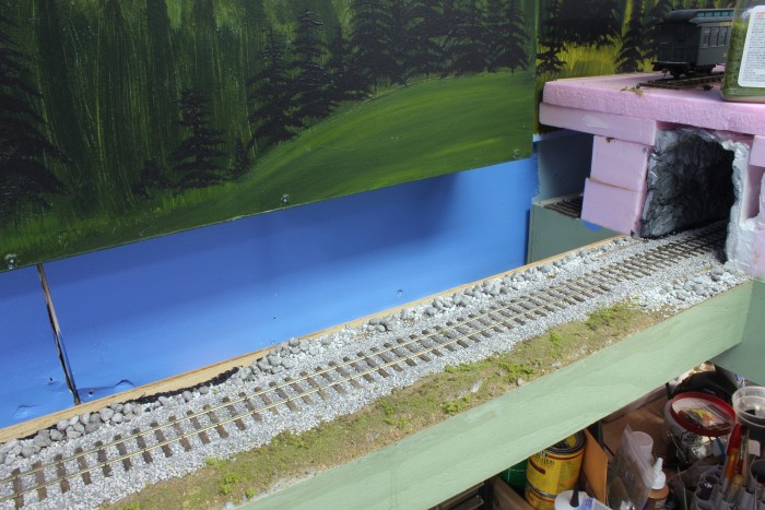
Building the Cliffs of Dover – Part 2
It’s been way too long from my last update but some progress has been made this year. I’ll post the changes as I get around to doing them. Hopefully It won’t take long. So here is the first update of the year.
The cliffs were done and completed in Part 1 and left to do was the track level. I had to do some thinking as the cliffs had to removable to allow access to the electrical panel so I needed to make sure that the ground scenery did not stick to the removable section. I would have hated to complete the scenery only to rip out some trees the first time I needed to remove the section.
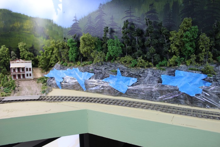
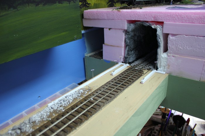
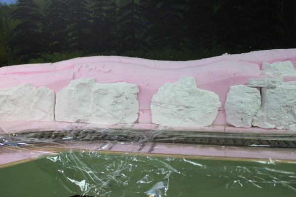
To begin I needed to separate the removable section from the track section so that once done the removable section will still be removable. I used saran wrap as the separation media to do this. In order to keep the wrap out of the way I tapped it to the rock face. Here is the left hand side of the rock face.
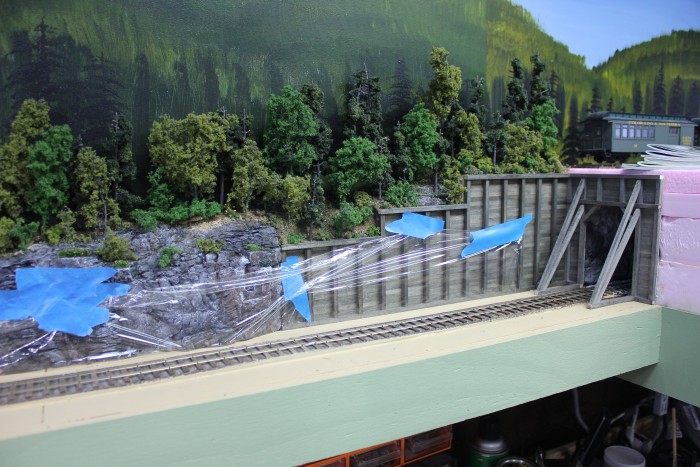
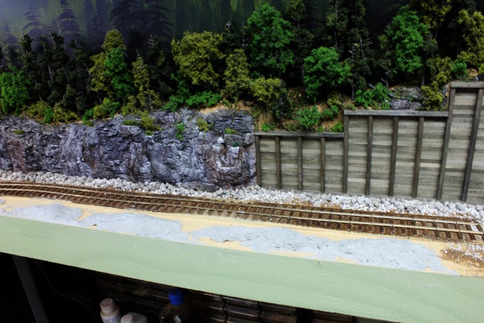
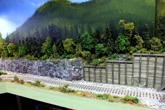
The right hand side of the rock face including the tunnel portal. Talus was added between the rock face / retaining wall and the track. Three sizes of the Woodland Scenics grey ballast was used in this step.

Once dry the cliff face was removed I painted the back edge of the talus with flat black paint in case gaps showed to when the cliffs were reinstalled. Before the cliff face was removed I traced the edge of the tunnel portal, retaining wall and portal supports.
I pinned styrene strips where the tunnel portal, retaining wall and portal supports go so that when the ground cover is added these areas will be kept free of the ground cover. Before the styrene strips were pinned in place I covered them with petroleum jelly so the glue would not stick to the styrene.
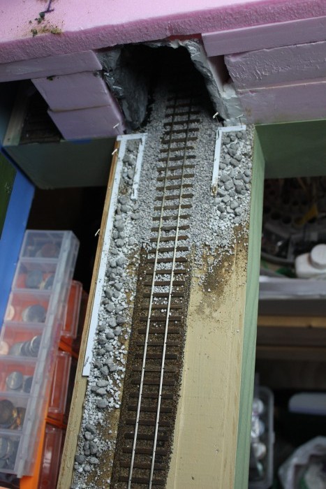
The talus and ballast added to the tunnel portal area of the cliffs. I found the talus to be to light so I added a couple of washed of A/I (alcohol/ink) to darken it up and make it closes to the colour of the cliff face.
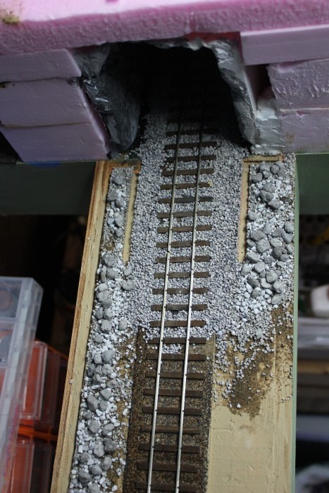
Once everything was dried I removed the styrene strips.
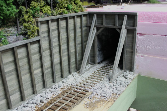
At this point I reinstalled the rock face / retaining wall / tunnel portal to see if it could be reinstalled easily and to see how it looked. It fit like a glove.
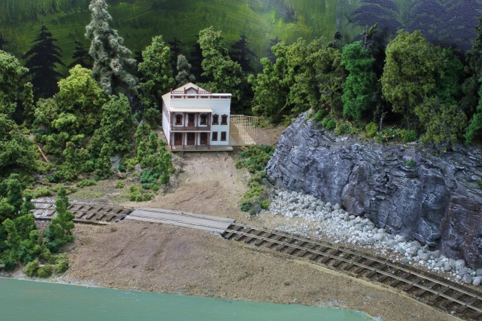
I mixes up some “ground goop” (recipe below) to add some elevation to the area and bring the road to the cabin up to the same level of the track. (The N scale building shown in these photos have been replaced with a HO scale cabin) One of the features I really like about the “ground goop” is that it takes a few days to completely dry, so if you go back a day later and you want to make changes it is a really easy process.
I had a little of the “ground goop” left over so I added some elevation changes in front of the rock face and tunnel portal.
While the goop was still wet I added full strength white glue to the areas without the goop and added my base ground cover, sand and brown sanded tile grout. I only use a little of the grout to act as a binder and glue for the scenery material.
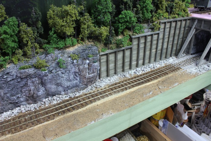
I did the same to the area in front of the rock face / retaining wall. I wasn’t worried about the goop showing through the ground cover as the grey colour looks like rock outcroppings.

THe next step was to add the ballast. Once the ballast was added and blued into place I added some “greenery”. I also added this in the completed area behind the track to tie everything together.
The “greenery” was added to the area in front of the rock face / retaining wall. At this point I misted the area with 99% isopropyl alcohol (wet water) and added a 50/50 mixture of white glue/water to glue everything in place.
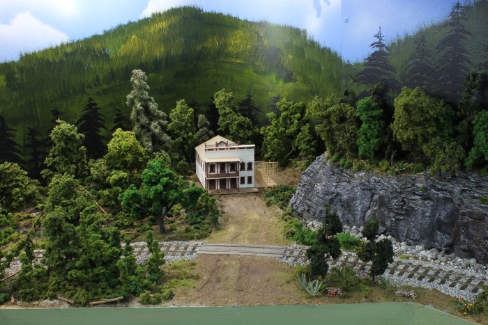
Trees were added at the side of the road to the cabin. This area was far enough away from the wall that removal of the cliff face was possible without damaging the trees.
Bushes shrubs and flowers were added to complete the scene.
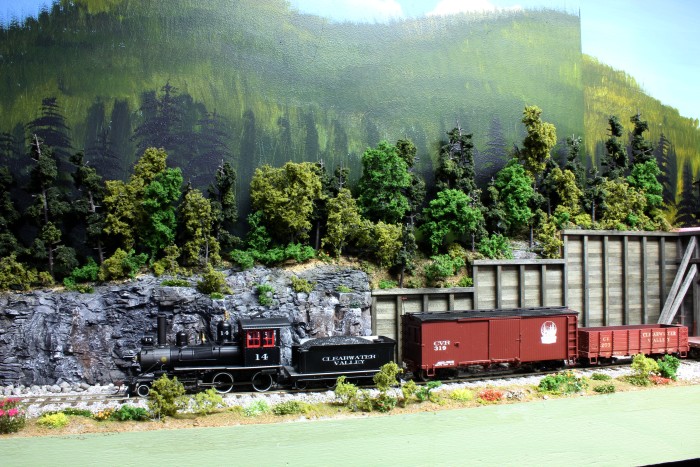
Here is train #21 on its way to Mara running through the completed scene. At this point I have one corner of my layout completely scenic and I’m really liking how it looks.
“Ground Goop” recipe
Grey Celluclay (this is a paper product available in craft stores like Michael’s)
White glue
Water
Javal
To make put a handful of Celluclay in a mixing bowl and add a dollop of white glue. I just turn the gallon glue container on its side until a blob of glue falls out, nothing is exact here. The white glue acts as a binder. While mixing in the glue I add water till I reach the consistency of thick oatmeal. Finally I add a couple of drops of Javal to the mix. The Javal prevents mold from growing on it during the drying process.
Building the Cliffs of Dover – Part 1
OK, it’s not quite the cliffs of Dover but what I needed to build is a removable piece of scenery in front of the electrical panel. In part 1 I’ll show how I did the cliffs themselves and part 2 will cover the scenery involved around the tracks and still have the section removable.
First off, here is the bare canvas or the starting point.


Seeing as the removable section is only 2″ deep, 1″ thick foam was used to create the land form. Seeing as the tunnel portal/retaining wall is a major feature along this section and will determine the final height of the section it was put in place.

Using a pencil a rough outline of the top of the cliff was added to the foam and then cut out.

The second layer of foam is cut out and glued to the back layer. At this point I glued the retaining wall to the foam.
Saran wrap was added between the removable section and the roadbed so that glue and such will not “glue” the removable section to the roadbed. I made some rock castings using some of the rock molds I acquired years ago that are made by Woodland Scenics. Plaster of Paris was used as the casting material. These castings were glued to the foam using white glue.

Spackling compound was used to fill in the areas between the rock castings. Not sure if I would so this again as the spackling compound took a couple of days to thoroughly set.

I also has some of Woodland Scenics’ pigments that I wanted to try out. To start, a wash was made using “slate grey” and everything was given a coat of this wash. I then made up washed of “raw umber” and “burnt umber” and stained portions of the rocks. Interesting side note was that the plaster of paris and the lightweight spackle took the stains differently which further added to the variety of colour.

Titanium white was then dry brushed on the rocks to blend everything together.
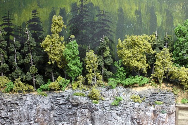
“Greenery” was added to the top of the cliffs and to the nooks and crannies on the rock face. The evergreens and other trees are Woodland Scenics products and the ground cover is a combination of Woodland Scenics and Scenic Express products.

An overall view of the cliffs.
That’s it for part 1
Clearwater gets a team track
After a few operating sessions it became plain that the team track arrangement was not working out very well. I decided to add the team track as a way of generating a more varied rolling stock mix on the layout and the siding to Adams Stave & Box Co. Seemed to be the logical location.

- The original location of the team track
But as it turns out it turned into an operational nightmare. Let me explain, Clearwater is the major switching town on the railway that contains the most industries. All train movements are dictated by the time it takes to do the switching in Clearwater. Eastbound trains were always delayed in Mosquito Flats waiting for the westbound train to finish its work. In order to even out the switching I decided to add a team track spur at the station.

- New location of the team track
I had an operating session this past Friday and the results were encouraging. Relocating the team track resulted in fewer moves required to do the switching in Clearwater and made for a more efficient operating scheme. While the eastbound trains still had to wait in Mosquito Flats, the wait was considerably shorter.
Here are a couple of construction pictures of the team track being added at the station.

- The rails and ties removed at the switch location

- The wood ties added, sanded and stained

- The switch completed

- The first cars on the team track