Building the Turntable at Mara – Part 1 (the bridge)
The turntable pit in Mara has been in place for a few years now bit hasn’t been completed because of a couple of small design flaws that makes the turntable unreliable. Seeing as I am now having operating sessions I really need a way to turn locomotives without the hand of God involved.
I decided to write this up in three parts, part one will be about fixing the problems with the Bridge, part two will show how I built the deck and part three will be how I powered it.
I am using the Walthers 90ft turntable (HO scale) which works out to 48ft in O scale which is the maximum lengths of my locomotives. The issues I found with the turntable is as follows;
- The walls of the pit were not 90 degrees and had a slight taper which caused the bridge to bind in certain locations.
- The wheels that rode on the pit rails were tapered.
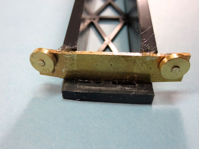
A close-up of the wheels that ride on the pit rail, as you can see from the photo, the wheels are not flat.
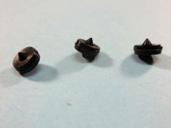
A close up of the the wheels removed from the bridge.
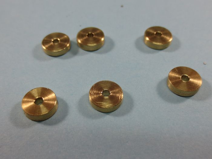
I decided that I would make new wheel assemblies to correct this problem. Using a vernier calliper the diameter of the existing wheels were measured and new wheels were turned on a lathe.
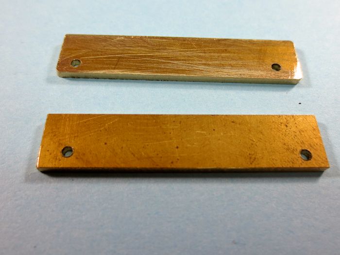
Next brass plates to make the brackets were made to hold the wheels in place on the bridge.
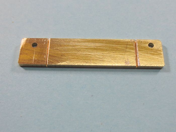
I cut a slot about half way through the brass plates so that they could be bent to match the diameter of the pit rail as the wheels need to be running perpendicular on the pit rail and not on an angle.

Once the plate was bent the wheels were attached. I used brass rod for this and I attached the wheels in the following matter. I put the brass rod into the hole flush with the backside of the plate and soldered the the rod to the plate. I then cut the rod about 1/16″ longer than the width of the wheel. Once the wheel was installed on the rod a jeweller’s hammer was used to add a pien at the end of the rod to make sure that the wheel would stay on the pin.

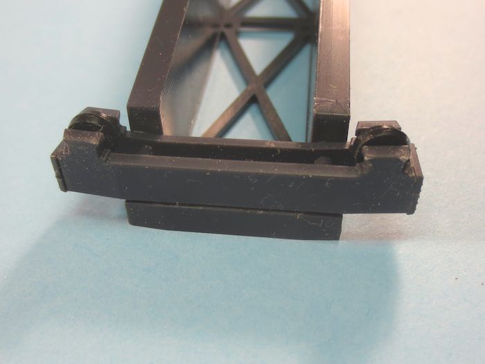
The old bracket and wheel assemblies were removed from the bridge and filed square.
The new bracket and wheel assemblies were epoxied to the bridge. You will notice that there is no outer bracket on the new assembly. THis was done deliberately so that there would be no binding of the new brackets on the pit walls. I could have made narrower wheels and add the outer bracket, but I wanted as much surface area as possible so that there was no chance that the wheels would fall off the pit rail and to allow for any inconsistencies in the diameter of the pit that could have been caused in the moulding process.
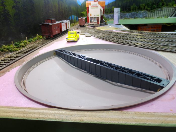
The bridge with it’s new wheel assemblies installed in the pit. I can now turn the bridge in circles with one finger in either direction with no binding whatsoever.
Now that I can get the turntable to operate reliably the next step will be to build the Deck that will go on the top of the bridge. I’ll show how I did this in part two of this turntable saga.