Welcome to the Clearwater Valley Railway Co. Construction Blog
Welcome to my layout construction blog. Seeing as I have finally started construction on the Clearwater Valley Railway I thought I would keep a running record of the construction of the layout with a blog. I plan to update the blog at least one a month, maybe more often if a lot of progress is made in a short period.
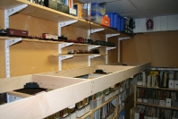
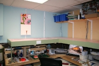
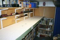
Before construction could begin on the layout I decided it was time to clean up and reorganize the layout room. I bought adjustable shelving from Ikea to hold my magazine and book collection. It’s amazing how much one can accumulate over the years. A metal drawer system was purchased from Lee Valley to store tools and modeling supplies. The drawers are available in 1″, 2″ and 3″ depths. By building a box with 1″ groove spacing to hold the shelves it is a versatile system. A 6 drawer unit was bought from Ikea to hold my “raw” modeling supplies (styrene, scale wood etc).
One thing I noticed was that the industrial carpet I was using had seen better days (I’m being nice here) and I had to do something about it when the vacuum cleaner caught a loose strand and before I knew it I blew a belt. What a lovely smell burnt rubber has. At least the vacuum cleaner is back in working order after removing what seemed like miles of carpet strands and replacing the belt. Home Depot sells 24″ x 24″ x 1/2″ interlocking foam pads that work well for me as it is very comfortable to stand on and doesn’t transmit the coldness of the concrete floor beneath it. This now is installed on the floor.
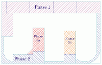
With the cleaning, “purging” and organizing completed it was time to construct the layout. The plan is to build the layout in three phases. Phase 1 is “L” shaped 6″-0″ x 16′-10″ and is from the Okanagan Valley Lumber Company Camp #2 to Clearwater. Phase 2 will consists of completing the loop and the town of Mara Lake. Phase 3 will be the town of McLure.
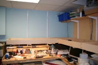
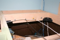
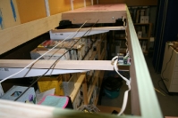
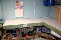
First thing that had to be done was install the wall brackets and standards. Layout height is fixed at 49″ above the floor. This height was determined by the clearance required to clear the electrical panel. The longest bracket I could find at my local Home Depot was 18 inches while my modules will be 24″ wide. This was solved by buying 1″ x 2″ hardwood and screwing to the brackets. Bench work was constructed using 2 feet by 4 feet modules constructed using 3/4″ furniture grade plywood ripped in 4″ wide lengths. This was cut glued and screwed together. I have found that building the bench work this way lets you build the framing on the floor and then it’s an easy matter to bolt them together.
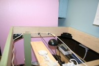
Once the modules were in place and bolted together it was time to install the bus and loconet wiring for the DCC system. Seeing as this is a permanent setup all that was need was to drill holes though the modules and running 12 gauge stranded wires for the bus wiring. For the loconet wiring one infrared jack and three modified telephone jacks were used for the other controller plug in stations. The modified telephone jacks were made from adding 2 pins from a donor plug to make the 6 pin plug required for the loconet connection. The 4 pin telephone jacks are readily available at our local dollar store. Because it takes three 4-pin plugs to make two 6-pin plugs the unit price for the 6-pin plugs is $1.50 each. You have to like those prices. This is the same system that it used at the local modular group I belong too and there have not been any issues using these plugs (disclaimer: we use batteries in all of the controllers used at the club).
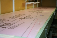
Once the wiring was installed it was time to install the “pink desert”. 2″ polyurethane foam is used for the deck. This was cut to size and glued in place with polyurethane glue. Again this method works quite well with the module group, so why mess with success.
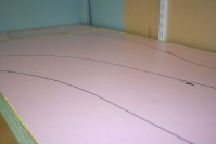
Seeing as I had drawn my layout in Autocad and have access to a 24″ wide plotter I plotted the drawing out full size, cut them to size and pinned it to the pink desert. A pounce wheel was used to transfer the track center lines to the pink foam. The drawings were removed and a marker was used to draw the center lines on the foam. I’m very happy transferring the track plan using this method and will use it on the other phases.
